1-wire keyboard
Home > Electronics > 1-wire keyboard
1-wire keyboard is a simple tool for calculating the resistors for a keyboard/resistor network on an A/D input.
1-Wire Keyboard is a calculator for embedded system designers to implement a keyboard/keypad using a single analog-to-digital converter (A/D) input. For larger keyboards, or keypads that require chording (more than one key pressed at a time) multiple A/D inputs can be used, each with a portion of your complete keypad.
There is a ‘Generate Code’ button. After you have named your keys and optimized your key placement and resistors, you can generate a C function to decode your keyboard. Please give me feedback if you have used this feature and if you had any issues with it. The current version doesn’t check key names for uniqueness or proper C variable syntax. If your compiler does not support a startup file that does initialization of variables at startup, you will have to change two lines and add the initialization as described in the comments of the generated code. The function that is generated is intended to be part of a real time clock service routine that will be serviced at 20 to a few hundred times a second. There are commented constants to adjust minimum key sense time.
1-Wire Keyboard supports from two (2) to 64 key keyboards; however, keyboards beyond 26 keys may be hard to realize with a single A/D input and low cost resistors. 1-Wire keyboards offer lower EMI than scanned keyboards, need fewer ESD protection components to implement, and also only require one pin on a microcontroller. If minimizing current consumption is a concern and the current drain of long key presses can not be tolerated, the keypad ground can be replaced with a second pin on the microcontroller configured as an open drain output. When reading a key this pin should be set to output a zero. The software can protect against excessively long key presses by allowing that pin to float (input mode, no pull down), just add this pin’s pull down resistance to your contact resistance value.
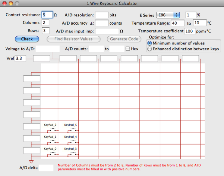
Enter your key switch worst case resistance, and keyboard size at the top left with the number of rows and columns needed. This will give you a rectangular array of keys, some of which you may not need. Control clicking (right clicking) on a key will remove or add that key.
Near the middle top is your A/D converter specifications. Make sure you enter the worst case A/D count error in the A/D accuracy field. This is often a sum of several error contributors on the data sheet. Make sure you are entering ‘counts’ and not ‘bits’ or you will make your job a lot harder. The last field is the maximum allowable A/D input impedance. This will be, for no key pressed, the maximum allowable resistor from the array to Vref.
At the right are the specifications for the family of resistors you want to use. The popup selects the set of values and fills in the typical tolerance. You can then change the tolerance if you need to. The default temperature coefficient is 100ppm; you may need to adjust this based on what resistors you pick. You may need to adjust this if your first attempt fails. For example Panasonic’s 1% ERJ family, it has 100ppm at high and low values, but from 100 ohms to 100k ohms it is 50ppm, so you can set your resistor temperature coefficient to 50 if you make sure your values are in that range. Also, if you are using metal film resistors, their temperature coefficients track over large ranges of values, so you can enter a much smaller temperature coefficient. Some other manufacturers may also have this characteristic. This could help solve overlapping A/D ranges for keys on some larger key count designs. Be sure to adjust the temperature range for your application.
If your keyboard is small you may want to try to get away with just three different resistor values, so leave the default radio button ‘minimum number of values’ selected. If your keyboard is more than eight (8) or so keys you will likely need to select ‘Enhanced distinction between keys.’
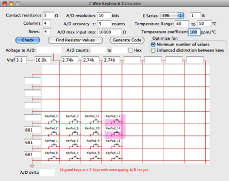
Now click ‘Find Resistor Values’. The algorithm is pretty quick on a modern desktop machine but takes quite a few seconds on a Raspberry Pi 3 with a large keypad.
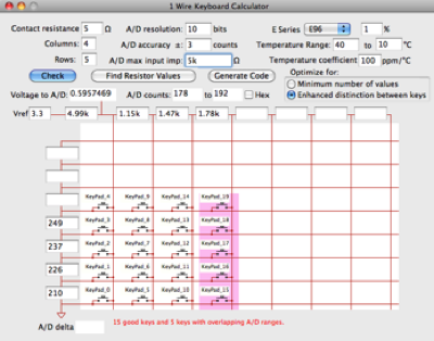
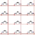
For keyboards with many keys you may see some pink highlighted keys. When A/D inaccuracy and resistors conspire against you, and some keys’ A/D ranges of a key overlap the A/D range of another key, those keys are highlighted in pink. You may get better results if you select the ‘Enhanced distinction between keys’ button at the right. This may do the trick, as below, in this 16 key example, but for larger keyboards you may need to do some additional work. If you choose, you may also name the keys as on the right below.

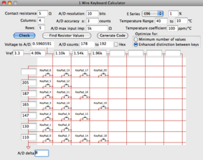
Let’s take a little larger keyboard, for example, of 20 keys. You may need to remove adjacent keys (right click on the key) and expand your array size to recover the lost keys. A 4 x 7 array with some offending keys (keys with possible non-unique A/D values) removed will give you 21 keys. To help figure out which key to remove, you can click on a pair of keys and see their worst case delta in the ‘A/D delta’ field at the bottom of the window. As long as you have a delta of one or more, those two keys are fine, because this is a comparison of the worst case minimum to the worst case maximum.
If you are designing a custom keyboard and the keys are arranged in circles, you can use my Device Placer to place the keys in perfect concentric circles if you are using Osmond PCB.
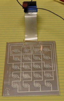
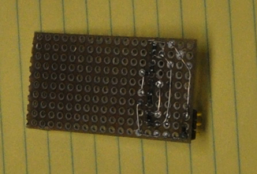
Above are pictures of one of my test keypads. The protoboard on the right has the eight resistors and connector for the keypad. Since the key layout is the same as a scanned keypad, a standard off-the-shelf membrane keypad was used. Although this protoboard has a three pin connector, I only needed two wires between my keypad and my main board. Only ground and the array output are needed; the pull-up resistor to your A/D reference voltage is on the board with the microcontroller. Another benefit is only one electrostatic discharge (ESD) device is needed for protection, as opposed to a scanned keypad that will need ESD protection for every column and row.
Note this architecture is just a resistor divider to the A/D reference for each key, so the measurement is ratiometric, meaning that the accuracy and drift of the A/D reference doesn’t affect the accuracy of the measurement.
Another advantage of this type of keypad is the ability to simply automatically simulate a series of key presses. The A/D input can be stimulated with a D/A channel from a data acquisition module or programmable power supply to simulate a near endless key sequence for software testing or product validation.
Below is a list of links to keypads that may work well with 1-wire keyboard.
See an example schematic in Capilano’s DesignWorks on my Schematics page, click here.


Visit my other pages: