Device Placer is a tool for placing components in concentric circles. Mainly for lighting, sensor, and keypad design work, it can handle any component. It will read in an Osmond netlist and save it with the location and rotation information for selected components. It is limited to four rings of components; if more rings are required, you can run the program again on your new netlist for up to four more rings.


Visit my other pages:


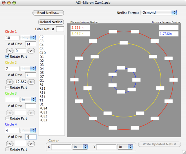
To use the program, you must have an Osmond PCB netlist. The Netlist Format popup only supports Osmond in this release, so it can be ignored. Click “Read Netlist...” button and find your netlist, click the “Open” button. Every component in your design should show in the tall list box. If you are just placing diodes, enter a D in the “Filter Netlist” edit field to remove everything that doesn’t start with a D. If your first circle is diodes and your second is I.C.s then, after placing all your diodes, replace the D in the “Filter Netlist” edit field with a U, and you will see all your I.C.s.
Now describe your circles of components, enter your diameter (millimeters or inches), the number of devices in that circle, any offset in degrees, and lastly whether or not the device should be rotated with the circle. There are two arrow buttons on either side of the offset angle. These buttons rotate the positions of the devices in 1/8 angular pitch increments. So, for example, if your circle has six devices, a 60 degree angular pitch, each press of the arrow buttons rotate your components by one eighth of your angle, or 60/8 degrees (7.5 degrees) in this example. You have these independent settings for each of your circles.
Now you need to place your devices in their locations. Simply drag a device from the list box to an edit field on one of the circles. If you have misplaced a device, control click on it to send it back to the list box.
Near the bottom of the window is the X and Y for the center of your circles. This reference is from the Osmond (0,0), or the lower left of the work area.
When you are finished, simply click the “Write Updated Netlist” button.
Device Placer expects the source netlist in a format similar to this example:

Part C2220R { Name C16 Value "4.7uF" }
Part C0603R { Name C17 Value "0.033uF" }
Part OSRAM-DRAG1 { Name D1 Value "White" }
Part SMB { Name D2 Value "1SMB5916B" }
Part OSRAM-DRAG1 { Name D3 Value "White" }
Part C2220R { Name C16 Value "4.7uF" }
Part C0603R { Name C17 Value "0.033uF" }
Part OSRAM-DRAG1 { Name D1 Value "White" Loc { 176.53m 228.6m 0.0 }} # 180 flip: 180.0 Location generated by Device Placer. See www.rau-deaver.org
Part SMB { Name D2 Value "1SMB5916B" }
Part OSRAM-DRAG1 { Name D3 Value "White" Loc { 202.565m 183.50606m 0.0 }} # 180 flip: 180.0 Location generated by Device Placer. See www.rau-deaver.org
The lines that Device Placer modifies are commented as in this example:


Device Placer
You can download my Osmond netlist report from my DesignWorks page.


Release 0.2.0 is a bug fix release with minor feature enhancements.
Allows for strings of spaces in net list for delimiters.
Allows window to be resized.
Up to 50 devices in three outer rings of components.
Net list comment now has 180° flip rotation value. So if your devices’ origin is in its center, you can use a text editor to do a 180° rotation
in your layout.