Schematic Collection
A collection of circuits for driving two LEDs from a single microcontroller pin. Combinations include different color LEDs and different operating voltages for the microcontroller.
Click Driving LEDs.cct.zip to download.Schematics_files/Driving%20LEDs.cct.zipSchematics_files/Driving%20LEDs.cct_1.zipshapeimage_2_link_0
A simple schematic for interfacing Maxim’s 1-wire products to a standard  9 pin serial RS-232 port. Includes a little program for very basic operations.
Click Maxim 1 wire interface.cct.zip to download.http://www.maxim-ic.com/products/1-wire/Schematics_files/Maxim%201%20wire%20interface.cct.zipSchematics_files/Maxim%201%20wire%20interface.cct_1.zipshapeimage_3_link_0shapeimage_3_link_1
An 18 key keypad that only uses three microcontroller pins. Supports three key chords for special/secret keystrokes. Requires a microcontroller with 10 bit A/D converter.
Click Keypad18.cct.zip to download.
Click here to see the 1-wire keypad design software.Schematics_files/Keypad18.cct.zip1-wire_keyboard.htmlSchematics_files/Keypad18.cct_1.zipshapeimage_4_link_0shapeimage_4_link_1
Home > Robert_Rau.html
Electronics >Electronics.html

Schematic Collection

All schematics below are in DesignWorks for Macintosh format. See my DesignWorks page here.

The schematic and layout for the RS-232 serial breakout board designed for the Serial Analyzer software. 
Click Serial AnalyzerHW.zip for the DesignWorks schematic and Osmond layout.
Click here to see the Serial Analyzer software page.Schematics_files/Serial%20AnalyzerHW.ziphttps://www.designworkssolutions.comhttps://www.osmondpcb.com/SerialPortAna.htmlSchematics_files/Serial%20AnalyzerHW_1.zipshapeimage_7_link_0shapeimage_7_link_1shapeimage_7_link_2shapeimage_7_link_3
email me.mailto:robertrau12@yahoo.com?subject=Schematics%20Page

Visit my other pages:

Electronic Design ToolsElectronics.html
Schmitt Trigger CalculatorSmTrig.html
Engineering Links for softwareLinks.html

I decided to try the iMall prototype PCB service when they offered a special price. Ten, 2 layer, 10cm by 10cm boards for $19.90. I had some requirements for some simple boards and this was the inspiration I needed. When you order boards from iMall, there is a interesting check box, “Open Source And Get 2 More Additional Boards.” This means I make my board available to others who made their board designs available to others. So a few people who order boards from iMall and check that check box might get one of my boards. So for you few people, here is the additional information you need to decide if it is worth anything to you, and if so, how you build the boards.

I sent my Gerber Files on December 29, 2013, and received my boards January 17, 2014.

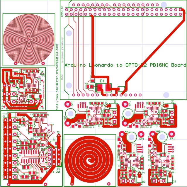
This board contains four designs (one four times) and two coils for sensor/isolation experiments. The coil in the upper left is about 35µH with 6.4Ω of resistance (1 oz. Cu). I used the script on this page to generate it.

  1. 1)Single servo two input multiplexer.

  2. 2)Quad servo two input multiplexer.

  3. 3)Four copies of a PWM servo channel to 5 amp MOSFET driver.

  4. 4)An adapter to control a OPTO-22 PB16HC board from a Arduino Leonardo board.

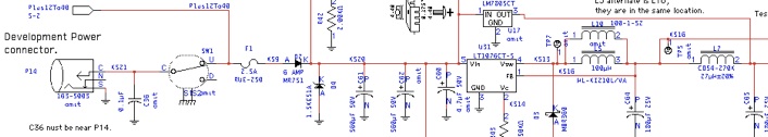
Although there are several servo multiplexers on the market, I wanted ones that didn’t use a microcontroller and also had ESD protection. As I test the boards I will post information about them here.

Here is a boost converter design that was designed with this tool. You can download the schematic in DesignWorks format here: MC3406xExample.cct.zip.MC34063_boost.htmlSchematics_files/MC3406xExample.cct.zipSchematics_files/Driving%20LEDs.cct_2.zipshapeimage_12_link_0shapeimage_12_link_1
Schematic CaptureSchematicCaptureLinks.html

I am putting up more information about my hardware projects. I am working on a HAT board for the raspberry Pi Zero. Look at it here.